Definition: A power system can be defined as a system that deals with the principles
of generation, transmission, distribution, and utilization of electrical energy.
The single line diagram of a power system network is as shown below
Generally, most of the time the power system network operates in normal conditions i.e the electrical quantities like voltage, current, and frequency are within the specified limits. But sometimes the network may experience some abnormal conditions in the electrical quantities due to the occurrence of faults. Now, we cannot stop the occurrence of these faults since the overhead lines are exposed to atmospheric conditions.
Classifications of faults
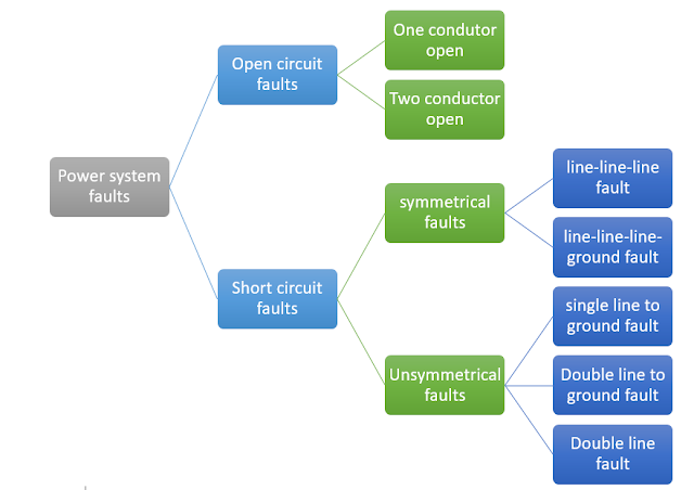
The electrical faults are generally classified as:
- Open circuit faults
- Short circuit faults
Open circuit faults occur in series with lines so they are generally called series faults. these faults occur due to the melting of conductors, snatching of conductors due to wind, or opening of the circuit breaker.
Short circuit faults occur between lines or line to ground, so they are referred to as shunt faults. Reasons for the occurrence of short circuit fault is as follows:
- Failure of insulator between the cross arm of tower and conductor.
- Falling of tree branches
- Birds, snakes bridging the gap between the cross arm and the conductor.
- Collapsing of supporting tower.
Consequences of Open circuit fault
During the normal operating conditions, the power which is supplied by the turbine(Pmech) is transmitted to load(Pelectrical). So, the net power
Pnet = Pmech – Pelectrical = 0
Hence, the machine will be neither be accelerated nor decelerated, and the speed of the generator will be the same as synchronous speed.
Now, let us consider an Open circuit fault in R-phase. So current through R-phase becomes zero but the remaining two phases will be delivering power to the load. Hence, the net electrical power transferred is reduced. Therefore, the net power pnet = pmech – pelec ≠0. and it is positive. So machine experiences acceleration.
Due to this acceleration, the speed of the generator(ꞷ) increases which increases the operating frequency which inturn increases the operating voltage.
Hence, the open-circuit fault will result in an overvoltage.
Due to this overvoltage, the voltage impressed on the insulator increases. This causes the damage/puncture of insulation.
Consequences of Short circuit fault
During the short circuit condition, the current flowing in the line is very high as compared to the normal rated current. Now, the electromagnetic torque(Te) developed in the generator is directly proportional to the current flowing in the conductor, so as current increases the torque Te also increases.
This electromagnetic torque creates opposition to the rotation of the generator. so with the increase in torque(Te) the speed of the alternator decreases, which decreases the frequency and in turn decreases the induced voltage(Eph).
Hence, the short-circuit fault will result in overcurrent.
This increase in current will yield two types of problems:
- Thermal stress: Due to very high current flowing in the line conductors, the power loss in the line increases. This increases the heat generated and excessive heat will lead to melting of the conductors and overheating of the insulators.
- Mechanical stress: Due to very high current the force experienced by the conductor increases.


Comments
Post a Comment